OLED Display
Show text and graphics on a 128x64 I2C OLED display with Arduino — first with no library at all, then with Adafruit SSD1306.
128x64 I2C OLED Display
We connect a 0.96" OLED display (SSD1306 controller) to an Arduino Nano over I2C and program it two ways. In variant 1 we send the commands to the display ourselves, using only Wire.h — this shows how the screen works inside. In variant 2 we use the Adafruit SSD1306 library, which gives us text in several sizes, lines, circles and animations in a few lines of code.
Got an ESP32?
The same project in MicroPython: OLED display on ESP32.
How it works
The screen has 128 × 64 = 8192 pixels. Each pixel is one bit (on or off), so the whole image takes 8192 / 8 = 1024 bytes.
The 64 rows are split into 8 pages of 8 rows each. One byte sent to the display lights up a vertical column of 8 pixels in the current page: bit 0 is the top pixel, bit 7 the bottom one.
          column 0    1   2  ...  127
         ┌───┬───┬───┬─────┬───┐
page 0   │   │   │   │     │   │  rows 0–7
page 1   │   │   │   │     │   │  rows 8–15
  ...    │   │   │   │     │   │
page 7   │   │   │   │     │   │  rows 56–63
         └───┴───┴───┴─────┴───┘
Every I2C transmission starts with a control byte: 0x00 means "a command follows", 0x40 — "data (pixels) follow". The display's I2C address is usually 0x3C, less often 0x3D.
Bill of materials
| Component | Qty | Notes |
|---|---|---|
| Arduino Nano (or Uno) | 1 | Tested on a CH340 Nano clone |
| 0.96" 128x64 I2C OLED display | 1 | SSD1306 controller, 4 pins |
| Jumper wires | 4 | M-F, or M-M with a breadboard |
| USB cable | 1 | Mini-USB for the Nano |
Wiring diagram
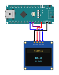
| Display pin | Arduino Nano / Uno | Arduino Mega |
|---|---|---|
| GND | GND | GND |
| VCC | 5V | 5V |
| SCL | A5 | 21 |
| SDA | A4 | 20 |
Pin order varies
On some modules the first pin is VCC, not GND. Read the labels on the board instead of relying on position.
Variant 1: no libraries
We only use Wire.h, which ships with the Arduino IDE.
Step 1. Sending a command
void cmd(uint8_t c) {
  Wire.beginTransmission(oledAddr);  // start talking to the display
  Wire.write(0x00);                  // "a command follows"
  Wire.write(c);                     // the command itself
  Wire.endTransmission();
}
Step 2. Initialisation
At power-up the display is off. We send it a command sequence from the SSD1306 datasheet. The most important ones:
0x8D, 0x14— turns on the "charge pump" that raises the voltage for the OLED. Without it the screen stays black.0x20, 0x00— horizontal addressing: after column 127 the cursor moves to the next page on its own.0xA1, 0xC8— orientation. If the text is mirrored or upside down, try0xA0/0xC0.0xAF— turns the screen on.
Step 3. The font
The display has no idea what the letter "A" is — it only knows pixels. We draw each letter from 5 columns (5 bytes), 7 pixels tall:
          col0 col1 col2 col3 col4
           7E   11   11   11   7E
 bit 0     .    ■    ■    ■    .
 bit 1     ■    .    .    .    ■
 bit 2     ■    .    .    .    ■
 bit 3     ■    .    .    .    ■
 bit 4     ■    ■    ■    ■    ■
 bit 5     ■    .    .    .    ■
 bit 6     ■    .    .    .    ■
PROGMEM keeps the font in flash memory — the Nano has only 2 KB of RAM but 30 KB of flash. We read it back with pgm_read_byte().
Step 4. Full code
// 128x64 I2C OLED display (SSD1306) with no extra libraries — Wire.h only
// Arduino Nano/Uno wiring: VCC -> 5V, GND -> GND, SCL -> A5, SDA -> A4

#include <Wire.h>
#include <avr/pgmspace.h>

uint8_t oledAddr = 0x3C;  // usually 0x3C, sometimes 0x3D (detected in setup)

// 5x7 font: space, 0-9, A-Z (each letter = 5 columns of 8 pixels)
const uint8_t font[][5] PROGMEM = {
  {0x00,0x00,0x00,0x00,0x00}, // ' '
  {0x3E,0x51,0x49,0x45,0x3E}, {0x00,0x42,0x7F,0x40,0x00}, // 0 1
  {0x42,0x61,0x51,0x49,0x46}, {0x21,0x41,0x45,0x4B,0x31}, // 2 3
  {0x18,0x14,0x12,0x7F,0x10}, {0x27,0x45,0x45,0x45,0x39}, // 4 5
  {0x3C,0x4A,0x49,0x49,0x30}, {0x01,0x71,0x09,0x05,0x03}, // 6 7
  {0x36,0x49,0x49,0x49,0x36}, {0x06,0x49,0x49,0x29,0x1E}, // 8 9
  {0x7E,0x11,0x11,0x11,0x7E}, {0x7F,0x49,0x49,0x49,0x36}, // A B
  {0x3E,0x41,0x41,0x41,0x22}, {0x7F,0x41,0x41,0x22,0x1C}, // C D
  {0x7F,0x49,0x49,0x49,0x41}, {0x7F,0x09,0x09,0x09,0x01}, // E F
  {0x3E,0x41,0x49,0x49,0x7A}, {0x7F,0x08,0x08,0x08,0x7F}, // G H
  {0x00,0x41,0x7F,0x41,0x00}, {0x20,0x40,0x41,0x3F,0x01}, // I J
  {0x7F,0x08,0x14,0x22,0x41}, {0x7F,0x40,0x40,0x40,0x40}, // K L
  {0x7F,0x02,0x0C,0x02,0x7F}, {0x7F,0x04,0x08,0x10,0x7F}, // M N
  {0x3E,0x41,0x41,0x41,0x3E}, {0x7F,0x09,0x09,0x09,0x06}, // O P
  {0x3E,0x41,0x51,0x21,0x5E}, {0x7F,0x09,0x19,0x29,0x46}, // Q R
  {0x46,0x49,0x49,0x49,0x31}, {0x01,0x01,0x7F,0x01,0x01}, // S T
  {0x3F,0x40,0x40,0x40,0x3F}, {0x1F,0x20,0x40,0x20,0x1F}, // U V
  {0x3F,0x40,0x38,0x40,0x3F}, {0x63,0x14,0x08,0x14,0x63}, // W X
  {0x07,0x08,0x70,0x08,0x07}, {0x61,0x51,0x49,0x45,0x43}  // Y Z
};

// Send a command: control byte 0x00 = "a command follows"
void cmd(uint8_t c) {
  Wire.beginTransmission(oledAddr);
  Wire.write(0x00);
  Wire.write(c);
  Wire.endTransmission();
}

// Set the cursor: column 0..127, page 0..7 (one page = 8 pixel rows)
void setPos(uint8_t col, uint8_t page) {
  cmd(0x21); cmd(col);  cmd(127);
  cmd(0x22); cmd(page); cmd(7);
}

void oledInit() {
  const uint8_t init[] = {
    0xAE,       // display OFF
    0xD5, 0x80, // clock frequency
    0xA8, 0x3F, // multiplex = 64 rows
    0xD3, 0x00, // no offset
    0x40,       // start line 0
    0x8D, 0x14, // enable charge pump (required!)
    0x20, 0x00, // horizontal addressing
    0xA1, 0xC8, // orientation (X/Y mirroring)
    0xDA, 0x12, // COM pins configuration
    0x81, 0xCF, // contrast
    0xD9, 0xF1, // pre-charge
    0xDB, 0x40, // VCOMH
    0xA4,       // show RAM contents
    0xA6,       // normal (not inverted)
    0xAF        // display ON
  };
  for (uint8_t i = 0; i < sizeof(init); i++) cmd(init[i]);
}

// Clear the whole screen: 128*64/8 = 1024 zero bytes
void clearScreen() {
  setPos(0, 0);
  for (int i = 0; i < 1024; i += 16) {  // the Wire buffer is only 32 bytes
    Wire.beginTransmission(oledAddr);
    Wire.write(0x40);                   // control byte 0x40 = "data follow"
    for (uint8_t j = 0; j < 16; j++) Wire.write(0x00);
    Wire.endTransmission();
  }
}

void drawChar(char c) {
  uint8_t idx = 0;                                   // default: space
  if (c >= '0' && c <= '9') idx = 1 + c - '0';
  else if (c >= 'A' && c <= 'Z') idx = 11 + c - 'A';
  else if (c >= 'a' && c <= 'z') idx = 11 + c - 'a'; // lowercase -> uppercase

  Wire.beginTransmission(oledAddr);
  Wire.write(0x40);
  for (uint8_t i = 0; i < 5; i++) Wire.write(pgm_read_byte(&font[idx][i]));
  Wire.write(0x00);                                  // gap between letters
  Wire.endTransmission();
}

void drawText(uint8_t col, uint8_t page, const char *s) {
  setPos(col, page);
  while (*s) drawChar(*s++);
}

// Check whether an I2C device answers at the given address
bool i2cPresent(uint8_t addr) {
  Wire.beginTransmission(addr);
  return Wire.endTransmission() == 0;
}

void setup() {
  Serial.begin(9600);
  Wire.begin();

  if (i2cPresent(0x3C)) oledAddr = 0x3C;
  else if (i2cPresent(0x3D)) oledAddr = 0x3D;
  else {
    Serial.println("OLED negasit pe I2C (0x3C/0x3D) - verifica firele SDA=A4, SCL=A5");
    return;
  }
  Serial.print("OLED gasit la adresa 0x");
  Serial.println(oledAddr, HEX);

  oledInit();
  clearScreen();
  drawText(0, 0, "SALUT");
  drawText(0, 2, "CERC DE INFORMATICA");
  drawText(0, 4, "2025");
  Serial.println("Text afisat");
}

void loop() {}
Why 16 bytes at a time when clearing?
The Arduino Wire library has a buffer of only 32 bytes. Anything beyond that limit in a single transmission is lost.
Each letter takes 6 columns (5 + one blank), so a row fits 21 characters and the screen 8 rows. The program uses 4.4 KB of flash and 562 bytes of RAM. The Serial Monitor (9600 baud) should show OLED gasit la adresa 0x3C ("OLED found at address 0x3C").
Variant 2: the Adafruit SSD1306 library
Step 1. Installing the libraries
In the Arduino IDE: Tools → Manage Libraries…, search for Adafruit SSD1306 → Install, and when asked about dependencies (Adafruit GFX Library, Adafruit BusIO) choose Install All. From the command line:
Step 2. The key idea: the buffer
The library keeps a copy of the screen in the Arduino's RAM (1024 bytes). Every drawing function only changes this copy; the image reaches the screen only on display.display().
  drawLine(), print(), drawCircle()...
              │
              ▼
   ┌─────────────────────┐   display.display()   ┌──────────┐
   │ buffer in RAM       │ ────────────────────► │  OLED    │
   │ (1024 bytes)        │        over I2C       │          │
   └─────────────────────┘                       └──────────┘
The upside: you can draw any pixel anywhere, and the image appears all at once, without flicker. The downside: the buffer takes half of the Nano's 2 KB of RAM.
Screen stays blank?
The most common mistake: you drew something but forgot display.display().
Step 3. Basic functions
| Function | What it does |
|---|---|
clearDisplay() |
clears the buffer |
setCursor(x, y) |
text position in pixels |
setTextSize(n) |
scales letters n times (1 = 6×8 pixels) |
setTextColor(c) |
SSD1306_WHITE or SSD1306_BLACK |
print() / println() |
like Serial — text, numbers, float |
drawPixel(x, y, c) |
one pixel |
drawLine(x0, y0, x1, y1, c) |
line |
drawRect / fillRect(x, y, w, h, c) |
rectangle / filled rectangle |
drawCircle / fillCircle(x, y, r, c) |
circle / disc |
fillTriangle(x0,y0, x1,y1, x2,y2, c) |
filled triangle |
display() |
sends the buffer to the screen |
Coordinates start at the top-left corner: x grows to the right (0–127), y downwards (0–63).
Step 4. Full code
The program loops through: text in three sizes → geometric shapes → inverted text → a 0–100% counter with a progress bar.
// 128x64 I2C OLED display (SSD1306) with the Adafruit SSD1306 + Adafruit GFX libraries
// Arduino Nano/Uno wiring: VCC -> 5V, GND -> GND, SCL -> A5, SDA -> A4

#include <Wire.h>
#include <Adafruit_GFX.h>
#include <Adafruit_SSD1306.h>

#define SCREEN_WIDTH   128
#define SCREEN_HEIGHT  64
#define OLED_RESET     -1     // the display has no separate RESET pin
#define SCREEN_ADDRESS 0x3C   // if it doesn't work, try 0x3D

Adafruit_SSD1306 display(SCREEN_WIDTH, SCREEN_HEIGHT, &Wire, OLED_RESET);

// 1. Text in several sizes
void demoText() {
  display.clearDisplay();
  display.setTextColor(SSD1306_WHITE);

  display.setTextSize(1);            // 6x8 pixels per letter
  display.setCursor(0, 0);
  display.println(F("Cerc de informatica"));

  display.setTextSize(2);            // 12x16 pixels per letter
  display.setCursor(0, 16);
  display.println(F("Salut!"));

  display.setTextSize(3);            // 18x24 pixels per letter
  display.setCursor(0, 38);
  display.println(F("2025"));

  display.display();                 // only now does the image reach the screen
}

// 2. Geometric shapes
void demoShapes() {
  display.clearDisplay();
  display.drawRect(0, 0, 40, 30, SSD1306_WHITE);           // rectangle
  display.fillRect(45, 0, 40, 30, SSD1306_WHITE);          // filled rectangle
  display.drawCircle(108, 15, 14, SSD1306_WHITE);          // circle
  display.drawLine(0, 63, 127, 34, SSD1306_WHITE);         // line
  display.fillTriangle(64, 36, 44, 63, 84, 63, SSD1306_WHITE);
  display.display();
}

// 3. Inverted text (black on white)
void demoInverse() {
  display.clearDisplay();
  display.fillRect(0, 20, 128, 24, SSD1306_WHITE);
  display.setTextColor(SSD1306_BLACK);
  display.setTextSize(2);
  display.setCursor(10, 25);
  display.print(F("INVERSAT"));
  display.display();
}

// 4. Counter with a progress bar
void demoCounter() {
  for (int i = 0; i <= 100; i += 5) {
    display.clearDisplay();
    display.setTextColor(SSD1306_WHITE);
    display.setTextSize(1);
    display.setCursor(0, 0);
    display.print(F("Incarcare..."));

    display.setTextSize(3);
    display.setCursor(30, 18);
    display.print(i);
    display.print('%');

    display.drawRect(0, 52, 128, 12, SSD1306_WHITE);           // bar outline
    display.fillRect(2, 54, map(i, 0, 100, 0, 124), 8, SSD1306_WHITE);
    display.display();
    delay(100);
  }
}

void setup() {
  Serial.begin(9600);

  // begin() allocates the 1024-byte buffer in RAM and initialises the screen
  if (!display.begin(SSD1306_SWITCHCAPVCC, SCREEN_ADDRESS)) {
    Serial.println(F("Eroare: SSD1306 nu a pornit (adresa sau firele?)"));
    for (;;);                        // stop the program
  }
  Serial.println(F("OLED pornit"));
}

void loop() {
  demoText();    delay(2000);
  demoShapes();  delay(2000);
  demoInverse(); delay(2000);
  demoCounter(); delay(1000);
}
F("text") keeps the string in flash instead of RAM — always worth it on a Nano. The principle behind any animation: clear → draw the new frame → display() → pause.
Comparison
| Parameter | Variant 1 (no library) | Variant 2 (Adafruit) |
|---|---|---|
| Flash | 4.4 KB (14%) | 15.6 KB (50%) |
| RAM | ~0.6 KB | ~1.5 KB (including the 1 KB buffer) |
| Positioning | column + page (8 px) | any pixel (x, y) |
| Font | only what you draw yourself | full ASCII, sizes 1–8 |
| Graphics | no | lines, circles, triangles, images |
| What you learn | how the display works | how to use it quickly |
RAM reported at compile time
For variant 2 the compiler reports only ~523 bytes of RAM, because the 1024-byte buffer is allocated later, in display.begin(). If you add many variables and begin() returns false, you have run out of memory.
Uploading to the board
- Tools → Board → Arduino Nano.
- Tools → Processor → ATmega328P (Old Bootloader) — for most Nano clones. If the upload fails, try ATmega328P.
- Tools → Port — the board's port (
COM3,/dev/cu.usbserial-…). - Upload, then Tools → Serial Monitor at 9600 baud.
arduino-cli compile -b arduino:avr:nano:cpu=atmega328old .
arduino-cli upload  -b arduino:avr:nano:cpu=atmega328old -p /dev/cu.usbserial-1460 .
Troubleshooting
| Symptom | Cause / fix |
|---|---|
not in sync: resp=0x00 on upload |
Choose ATmega328P (Old Bootloader) under Processor |
| "OLED negasit" / "SSD1306 nu a pornit" | Check the wires — swapped SDA and SCL is the most common mistake; try address 0x3D |
| Black screen, but the display responds | Missing 0x8D, 0x14 (variant 1) or display() (variant 2) |
| Text mirrored or upside down | Swap 0xA1 ↔ 0xA0 or 0xC8 ↔ 0xC0 |
| The Adafruit logo appears | begin() puts the logo in the buffer; call clearDisplay() before the first display() |
| Random pixels, image shifted by 2 px | The display has an SH1106 controller (usually the 1.3" ones), not SSD1306 — use Adafruit SH110X or U8g2 |
Exercises
- Variant 1: add
!,?,.and:to the font — draw them on paper first, on a 5×7 grid. - Variant 1: show the seconds since power-up (
millis() / 1000). Hint:itoa()turns a number into text. - Variant 2: a ball bouncing off the edges of the screen (variables
x,y,dx,dy). - Variant 2: a potentiometer on
A0— showanalogRead(A0)as a number and as a progress bar. - Variant 2: plot the
sinfunction across the full width of the screen.