OLED Display
Show text and graphics on a 128x64 I2C OLED display with ESP32 and MicroPython — first using only built-in firmware modules, then with the ssd1306 driver.
128x64 I2C OLED Display
We connect a 0.96" OLED display (SSD1306 controller) to an ESP32 over I2C and program it in MicroPython, two ways. In variant 1 we use only modules that already ship with the firmware — machine.I2C and framebuf — and send the commands to the display ourselves. In variant 2 we install the ssd1306 driver from micropython-lib, which does the same thing in one line.
Got an Arduino?
The same project in C++: OLED display on Arduino.
Description
The screen has 128 × 64 = 8192 pixels. Each pixel is one bit, so the whole image takes 1024 bytes. The 64 rows are split into 8 pages of 8 rows; one byte sent to the display lights up a vertical column of 8 pixels in the current page (bit 0 at the top, bit 7 at the bottom).
          column 0    1   2  ...  127
         ┌───┬───┬───┬─────┬───┐
page 0   │   │   │   │     │   │  rows 0–7
page 1   │   │   │   │     │   │  rows 8–15
  ...    │   │   │   │     │   │
page 7   │   │   │   │     │   │  rows 56–63
         └───┴───┴───┴─────┴───┘
Every I2C transmission starts with a control byte: 0x00 — "a command follows", 0x40 — "data (pixels) follow". The display's address is usually 0x3C.
Unlike the Arduino Nano (2 KB of RAM), the ESP32 has 520 KB, so we can comfortably keep a copy of the whole screen in memory and send it in one go.
Materials
| Component | Qty | Notes |
|---|---|---|
| ESP32 DevKit V1 | 1 | With MicroPython firmware |
| 0.96" 128x64 I2C OLED display | 1 | SSD1306 controller, 4 pins |
| Jumper wires | 4 | M-F, or M-M with a breadboard |
Wiring
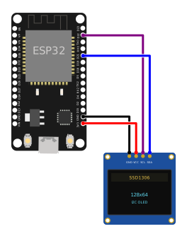
GPIO 22 (SCL) and GPIO 21 (SDA) are the usual ESP32 I2C pins. The OLED module works at both 3.3 V and 5 V; powering it from 3V3 keeps the SDA/SCL logic levels safe for the ESP32.
Wiring diagram
Variant 1: built-in firmware modules only
machine.I2C talks to the display, while framebuf draws text, lines and rectangles in memory. The framebuf.MONO_VLSB format means "one byte = 8 vertical pixels, bit 0 at the top" — exactly how the SSD1306 organises its memory. That is why the buffer can be sent to the display as is, with no conversion.
# 128x64 I2C OLED display (SSD1306) on ESP32 — machine.I2C and framebuf only
# Wiring: VCC -> 3V3, GND -> GND, SCL -> GPIO 22, SDA -> GPIO 21
from machine import Pin, I2C
import framebuf

ADDR = 0x3C

INIT = (
    0xAE,        # display OFF
    0xD5, 0x80,  # clock frequency
    0xA8, 0x3F,  # multiplex = 64 rows
    0xD3, 0x00,  # no offset
    0x40,        # start line 0
    0x8D, 0x14,  # enable charge pump (required!)
    0x20, 0x00,  # horizontal addressing
    0xA1, 0xC8,  # orientation (X/Y mirroring)
    0xDA, 0x12,  # COM pins configuration
    0x81, 0xCF,  # contrast
    0xD9, 0xF1,  # pre-charge
    0xDB, 0x40,  # VCOMH
    0xA4,        # show RAM contents
    0xA6,        # normal (not inverted)
    0xAF,        # display ON
)

i2c = I2C(0, scl=Pin(22), sda=Pin(21), freq=400000)
print("Dispozitive I2C:", [hex(a) for a in i2c.scan()])  # 0x3c should appear


def cmd(c):
    i2c.writeto(ADDR, bytes((0x00, c)))  # 0x00 = "a command follows"


def show(buf):
    for c in (0x21, 0, 127, 0x22, 0, 7):  # all columns, all pages
        cmd(c)
    i2c.writevto(ADDR, (b"\x40", buf))    # 0x40 = "data follow", then 1024 bytes


for c in INIT:
    cmd(c)

buf = bytearray(128 * 64 // 8)  # 1024 bytes = the whole screen
fb = framebuf.FrameBuffer(buf, 128, 64, framebuf.MONO_VLSB)

fb.fill(0)
fb.text("Salut!", 0, 0)
fb.text("Cerc de", 0, 16)
fb.text("informatica", 0, 26)
fb.rect(0, 44, 128, 20, 1)
fb.text("ESP32 2025", 24, 50)
show(buf)
The framebuf font is 8×8 pixels, so a row fits 16 characters and the screen 8 rows. Every change reaches the screen only after show(buf).
Why writevto?
writevto sends several chunks back to back in a single I2C transmission: first the 0x40 control byte, then the buffer. This way we don't have to glue the 1024 bytes onto b"\x40" and create a new copy on every frame.
Variant 2: the ssd1306 driver
The ssd1306 driver from micropython-lib contains exactly the code from variant 1, wrapped in a class. The class inherits from framebuf.FrameBuffer, so it has the same drawing functions, plus show().
Installing the driver
- Thonny: Tools → Manage packages…, search for
ssd1306, click Install. - mpremote (board connected over USB):
Code
# 128x64 I2C OLED display (SSD1306) on ESP32 with the ssd1306 driver from micropython-lib
# Wiring: VCC -> 3V3, GND -> GND, SCL -> GPIO 22, SDA -> GPIO 21
# Install the driver: mpremote mip install ssd1306  (or Thonny -> Manage packages)
from machine import Pin, I2C
from time import sleep
import ssd1306

i2c = I2C(0, scl=Pin(22), sda=Pin(21), freq=400000)
print("Dispozitive I2C:", [hex(a) for a in i2c.scan()])  # 0x3c should appear

oled = ssd1306.SSD1306_I2C(128, 64, i2c)


def demo_text():
    oled.fill(0)
    oled.text("Cerc de", 0, 0)
    oled.text("informatica", 0, 10)
    oled.text("Salut, ESP32!", 0, 30)
    oled.text("2025", 0, 50)
    oled.show()


def demo_shapes():
    oled.fill(0)
    oled.rect(0, 0, 40, 30, 1)            # rectangle
    oled.fill_rect(45, 0, 40, 30, 1)      # filled rectangle
    oled.ellipse(108, 15, 14, 14, 1)      # circle (MicroPython 1.20+)
    oled.line(0, 63, 127, 34, 1)          # line
    oled.show()


def demo_counter():
    for i in range(0, 101, 5):
        oled.fill(0)
        oled.text("Incarcare...", 0, 0)
        oled.text("{:3d}%".format(i), 48, 24)
        oled.rect(0, 52, 128, 12, 1)                  # bar outline
        oled.fill_rect(2, 54, i * 124 // 100, 8, 1)   # the bar
        oled.show()
        sleep(0.1)


while True:
    demo_text()
    sleep(2)
    demo_shapes()
    sleep(2)
    demo_counter()
    sleep(1)
Basic functions
| Function | What it does |
|---|---|
fill(c) |
fills the whole screen (0 = black, 1 = white) |
text(s, x, y, c=1) |
text with an 8×8 font, starting at pixel (x, y) |
pixel(x, y, c) |
one pixel |
line(x0, y0, x1, y1, c) |
line |
rect / fill_rect(x, y, w, h, c) |
rectangle / filled rectangle |
ellipse(x, y, rx, ry, c, f) |
ellipse or circle; f=True = filled (MicroPython 1.20+) |
scroll(dx, dy) |
shifts the whole content by dx, dy pixels |
invert(1) |
inverts the colours on screen |
contrast(0..255) |
brightness |
show() |
sends the buffer to the screen |
Troubleshooting
| Symptom | Cause / fix |
|---|---|
i2c.scan() returns [] |
Check the wires; swapped SDA and SCL is the most common mistake |
OSError: [Errno 19] ENODEV |
The display doesn't answer at 0x3C — see which address i2c.scan() shows (maybe 0x3d) and use it |
ImportError: no module named 'ssd1306' |
The driver isn't installed on the board (see "Installing the driver") |
AttributeError: ... 'ellipse' |
MicroPython firmware older than 1.20 — update it or stick to rect/line |
| Random pixels, image shifted by 2 px | The display has an SH1106 controller (usually the 1.3" ones), not SSD1306 — you need an sh1106 driver |
Exercises
- Show the temperature and humidity from the DHT22 sensor instead of fixed text.
- Build a clock: show
time.ticks_ms() // 1000(seconds since power-up), updated every second. - A ball bouncing off the edges of the screen (variables
x,y,dx,dy). - Plot the
math.sinfunction across the full width of the screen. - Use
oled.scroll(0, -8)to build a "terminal" where each new line pushes the text up.